
Lithium Batterie Ofen

Lithium Batterie Ofen
锂电池窑炉专用的耐高温光纤传感器!附保姆级安装使用方法The mainstream large-scale preparation method of lithium-ion battery positive electrode materials is high-temperature solid phase method (sintering). Among them, the main equipment of the sintering method adopts tunnel kiln (roller kiln), and its process mainly includes material filling, sagger conveying, sintering and cooling. In the entire process section, high-temperature optical fiber is used in sintering and cooling processes.
In the kiln sintering and cooling process, the sagger loaded with lithium-ion battery positive electrode materials is placed on the round roller of the kiln and transmitted by the rotation of the roller rod. In the control of the transmission process, it is necessary to monitor the rotation state of the roller rod in real time. In the preheating section of the kiln, the temperature in the kiln reaches about 300, and in the sintering section, the temperature in the kiln rises to about 600. In this high temperature environment, high-temperature optical fiber with high temperature resistance is required to detect the state of the roller rod sensor sheet.
Installation and debugging
① Installation of high-temperature optical fiber components
The optical fiber head is fixed with sheet metal parts. The processing size and installation hole position of the optical fiber head installation sheet metal parts at the transmitting and receiving ends are consistent. The sheet metal parts are fixed and calibrated by laser pen to ensure that the transmitting and receiving optical fiber heads can be effectively aligned. At the same time, it is recommended to swap the positions of the transmitting and receiving ends of the upper and lower pairs of optical fiber heads to ensure the stability of the detection of the two pairs of optical fiber sensors.

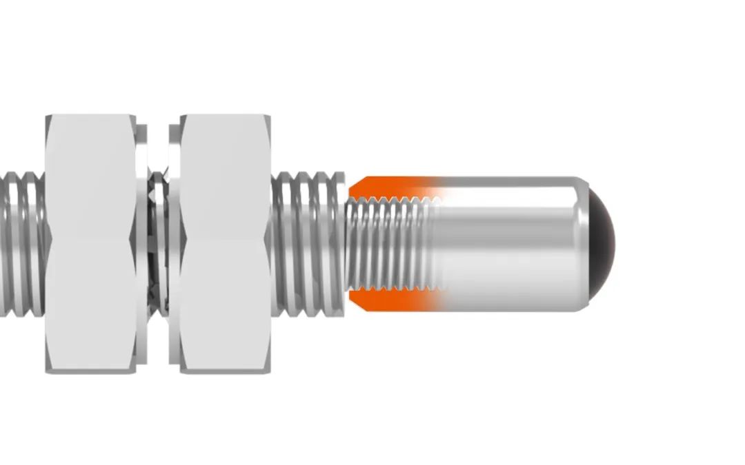
② Installation of focusing mirror
The focusing lens adopts a special high-temperature resistant lens. When installing, tighten the focusing mirror on the front thread of the optical fiber head to ensure the firmness between the focusing mirror and the optical fiber component to achieve the best detection performance and stability.
③ Connection between optical fiber amplifier and optical fiber component
When installing the optical fiber head and amplifier, first lower the optical fiber fixing rod, insert the optical fiber tail plug into the optical fiber port of the amplifier, ensure that the tail plug is inserted in place, and then pull the optical fiber fixing rod back to the top to prevent the optical fiber head from loosening.
④ Debugging of optical fiber amplifier
After the optical fiber head and focusing lens are installed and aligned, the amplifier is powered on for debugging. First, enter the [Basic Menu] interface of the PC1 amplifier, find the [Response Speed] item (rESP), enter the item and adjust the default parameter 3 gears to the maximum gear 7 gears;
After setting the response speed gear, enter the [Detailed Setting Menu], find the [Light Intensity] item, enter the item and adjust the gear to the maximum gear 3 gears.

After setting the above two parameters, return to the initial operation interface;

Threshold setting, when the optical fiber is not blocked, the amplifier detection value (red digital display value) at the 4m installation position is about 500, and the 6m detection position is about 200
Fiber optic amplifier PC1 data - 6m

When the fiber head is blocked by the roller sensor, the fiber optic amplifier detection value is about 0, and the threshold (green digital display value) is set to about 10% of the detection value. After setting the threshold, return to the initial operation interface for measurement.
Fiber amplifier PC1 data-4m

Summary of precautions for high-temperature fiber installation and testing
1. The installation of the transmitting and receiving fiber heads must ensure alignment to ensure the effective signal strength of long-distance measurement
2. When installing the fiber focusing mirror, it is necessary to ensure the tightness of the installation to ensure the stability of the measurement
3. When installing the fiber and amplifier, the fiber tail plug needs to be inserted in place to ensure the effective transmission of the amplifier light
4. When setting the fiber amplifier parameters, the response gear and light intensity gear must be adjusted to the highest gear to achieve the best performance of long-distance measurement
+86 18188641602

Akusense Technology Co., Ltd.