
How is this visual sensor achieved by determining the presence or absence of four buttons at once?
How is this visual sensor achieved by determining the presence or absence of four buttons at once?
How to quickly and stably detect whether all the buttons are assembled properly, given their different shapes, colors, and easily reflective surfaces?
The problem of missing small components on PCB boards has always been a "hidden killer" on electronic product assembly lines. Especially the buttons - with different shapes, colors, and easily reflective surfaces - how to quickly and stably check if all the buttons are assembled properly?
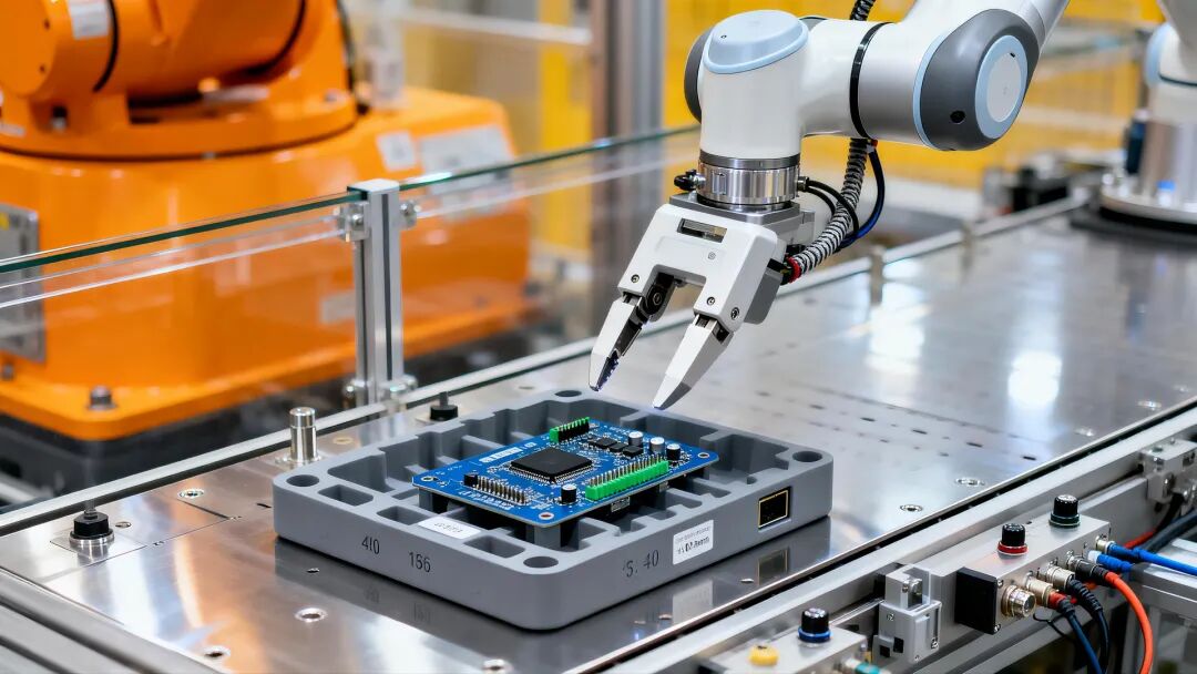
Today, engineers from Meiji Sensing bring a real on-site case to see how we won with one move using the VDS10 visual sensor.
Application scenario
There are 4 buttons on the PCB board, and it is necessary to reliably determine whether all 3 buttons are assembled in place without stopping the wiring.
Difficulty analysis
There are various types of buttons - different batches of boards have different shapes and colors of buttons;
The surface of the button has mirror reflection - under ordinary light source illumination, the high brightness reflection on the surface of the button will mask the real imaging features, leading to misjudgment;
High tempo requirement - real-time judgment needs to be completed during high-speed operation of the production line.
Selection Recommendation
For this scenario, we recommend the Meiji Vision Sensor VDS10 series as the core detection unit.
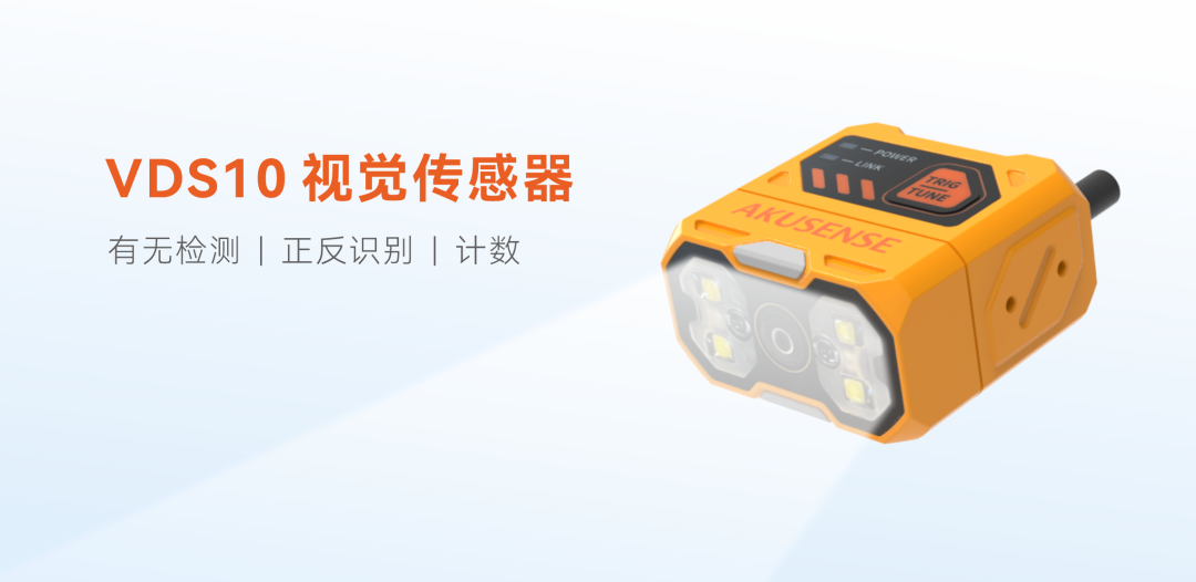
1. Sensor selection: VDS10-BQ0106-WP (with polarized white light model)
Considering the severe reflection on the surface of the buttons, under ordinary light sources, the button area will form a large area of overexposure, masking the true contour. Therefore, I specifically chose a model with a polarized white light source and installed a polarizer in front of the lens to effectively filter out specular reflection light, retaining only diffuse reflection components, significantly improving the grayscale contrast between the buttons and the PCB background, and making pattern recognition more stable
2. Focal length and installation distance: Select the 6mm focal length version, and set the working distance within the range of 40-300mm according to the actual site. While ensuring that the imaging field covers three buttons, obtain sufficient detail resolution

3. Detection tool: presence or absence of patterns
After the imaging is stable, enter the detection logic section. Although these three buttons have different shapes and colors, the internal contours and texture features of each button are relatively stable.
In the software tool, we have selected regions of interest (ROIs) for each key area and enabled the Pattern Tool - this tool searches for feature patterns that match the set template within the ROI. When no object that matches the pattern features is found in the target area, it is considered missing.
4. Peripheral Communication and I/O
Cooperate with the PLC signal interaction of the production line:
Network port: Connected to the workshop LAN via Ethernet for remote monitoring and detection of images by the upper computer.
RS232 serial port: Real time transmission of OK/NG results to the on-site industrial control computer for data traceability and statistics.
Power supply+IO: 24V DC power supply; Use two optocouplers to isolate the input and receive the production line trigger signal (such as the in place sensor signal), and transmit the judgment result to the rejection mechanism or alarm device through three non isolated outputs.
Application Effect
OK
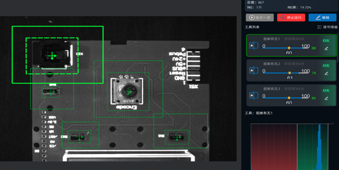
Three buttons fully assembled
NG
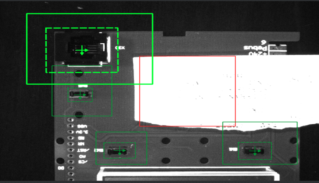
The middle button is missing
NG
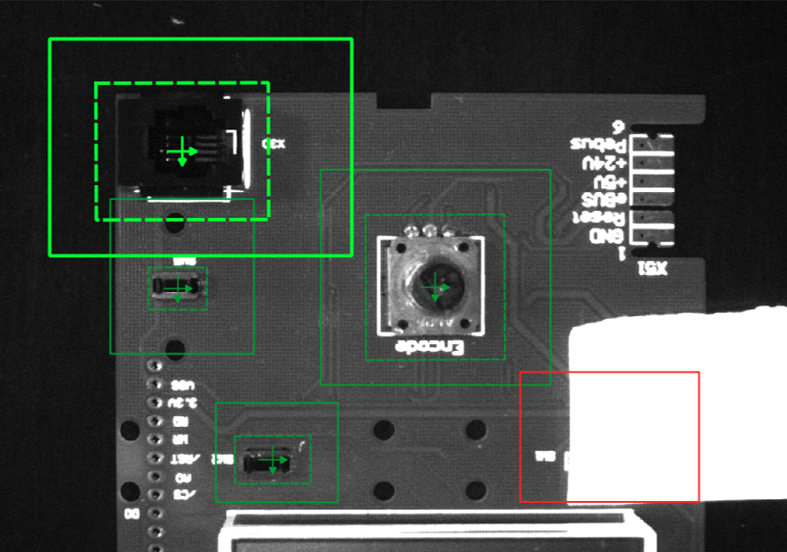
The middle button is missing
On site testing showed that the VDS10 is mounted on a bracket, facing the PCB board from top to bottom, and the drawing speed is very fast. It can completely keep up with the operating speed of the production line.
Due to the use of polarized light sources, the images captured by different batches and colors of buttons have good stability - bright and uniform, without high light interference, and the "Pattern Presence" tool can lock the real button features very stably, making the system run smoothly.
If you also face similar testing difficulties, please feel free to communicate with us! We will provide you with solutions to help your production line move towards intelligent upgrading!

扫码获取专属服务
+86 18188641602

Akusense Technology Co., Ltd.